This page is under construction.
2.72/2.720: elements of mechanical design
This class, taught by Proressor Marty Culpepper, covered "advanced modeling, design, integration, and best practices for use of machine elements, such as bearings, bolts, belts, flexures, and gears....based upon rigorous application of physics, mathematics, and core mechanical engineering principles." The goal of the semester-long team project was to "synthesize, model and fabricate a design subject to engineering constraints (e.g., cost, time, schedule)."
|
|
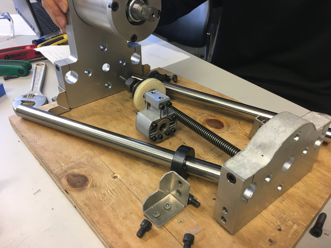
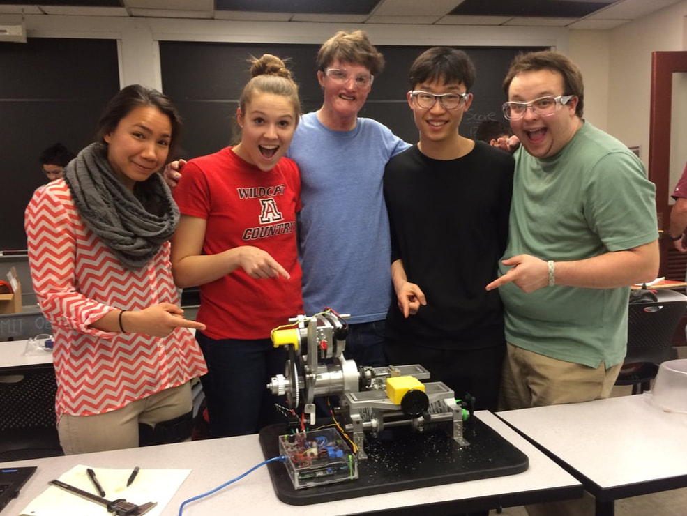
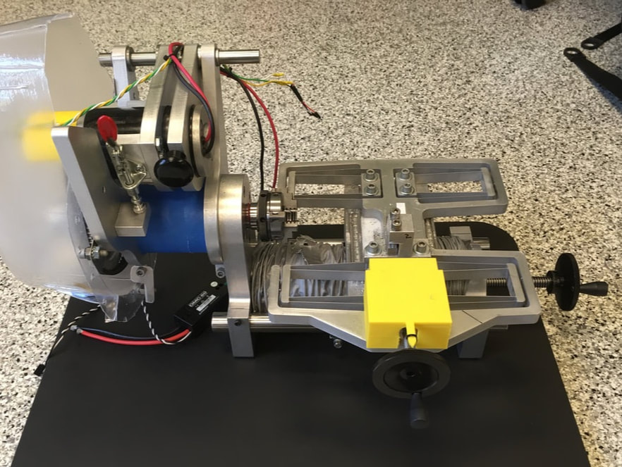
The main project for this class was to design and build a desktop lathe that is accurate to within 50 microns and capable of cutting a range of materials, from delrin to steel. We were given a specific set of requirements and constraints around which to design the lathe. At the end of the semester, our team of five won a class competition to turn a part that was graded based on time, dimensional accuracy, taper, and runout. Our lathe also had to pass a series of tests in which Prof. Culpepper dropped it from a distance, hit it with a sledgehammer, and rammed the tool into a par as the motor was running. The final test was to have a team member (me!) stand on the lathe and "ride" it while a teammate drove the x- and z-axes.
|
|
|
|
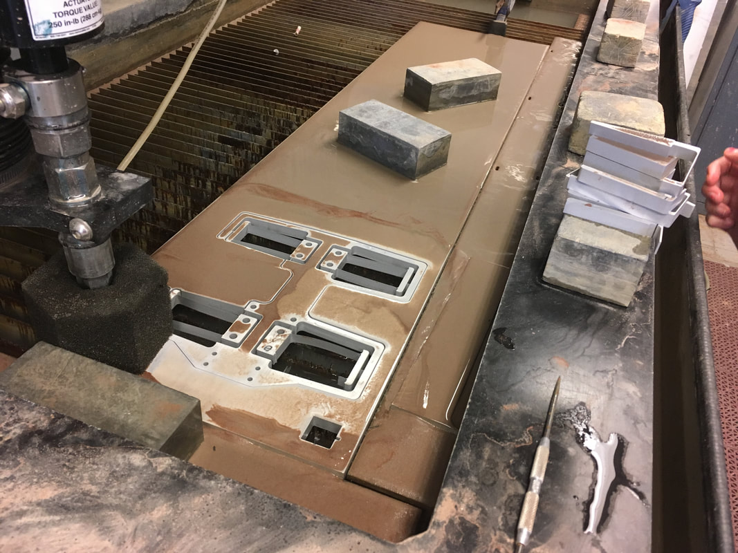
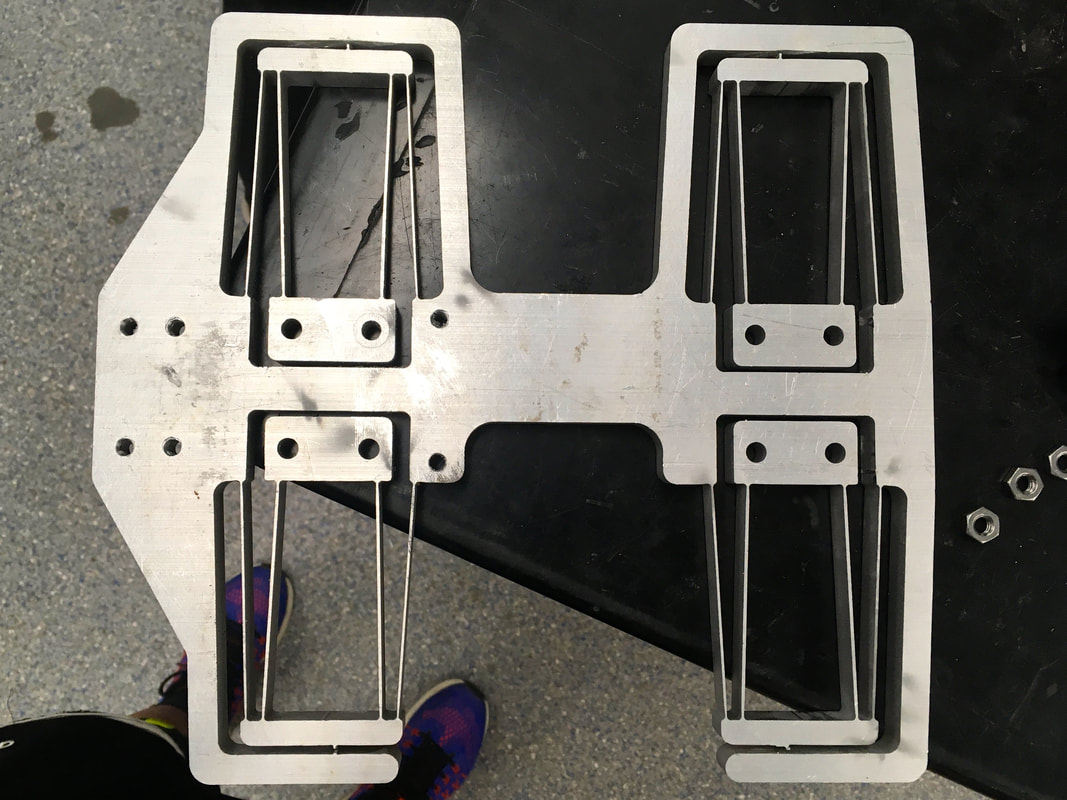
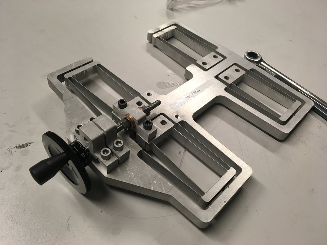
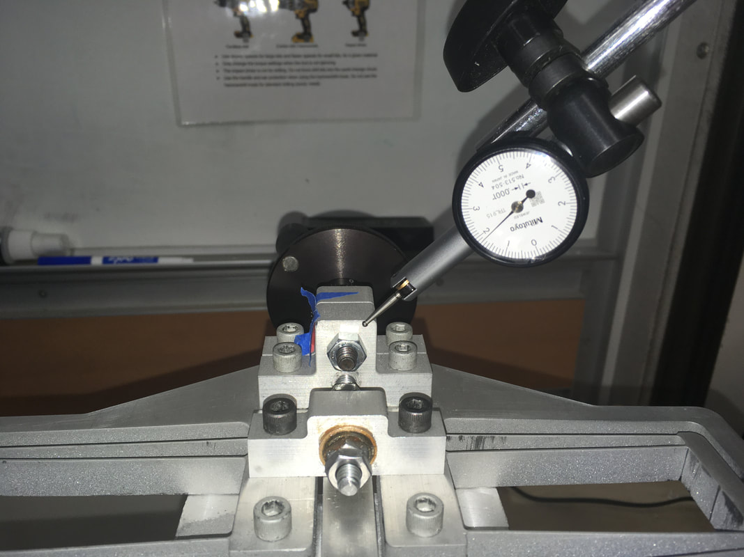
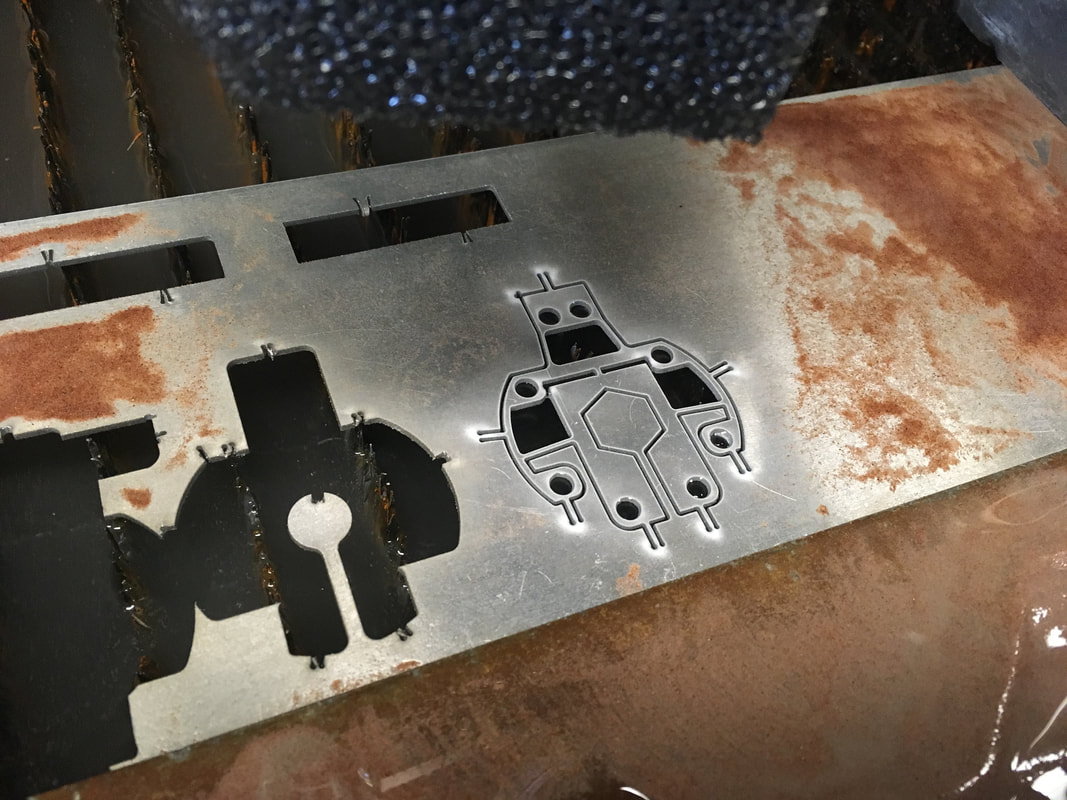
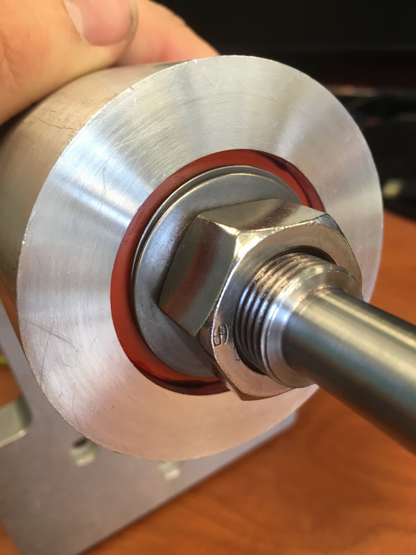
As the finite element analysis "guru," I was responsible for using FEA to iteratively converge on final values for the critical dimensions of the each of the flexure "beams." I also performed FEA analysis to verify that the flexures would not buckle under expected loads, would not fatigue under displacement over a predicted number of cycles, and that cross-slide vibration mode frequencies were safely away from the spindle speed. Finally, I was responsible for waterjetting and machining each of the flexures.
|
|
(Hover over images to see captions, click to enlarge.)