Note: I had to drop this class due to medical reasons. A large chunk of the preliminary mechanical design work is shown on this page, but unfortunately I was unable to complete the physical build.
2.70: precision PRODUCT design (spring 2016)
This class teaches the fundaments of precision product design, with an emphasis on optimizing accuracy, repeatability, and precision through an iterative analysis approach. We learn the physics and mechanics that apply to each of the topics (linkages, power transmission, screws and gears, actuators, structures, joints, bearings, error apportionment, and error budgeting), and how to apply them to analysis and machine design decisions.
|
The semester-long project was to design a one-to-three axis machine of our choice. I chose to design a fused filament fabrication (FFF) 3D printer. Instead of the traditional orthogonal 3-axis layout, I decided to use the delta linear design, which (aside from having fascinating kinematics) meant that the design of each of the three axes would be identical.
Key design steps:
|
|
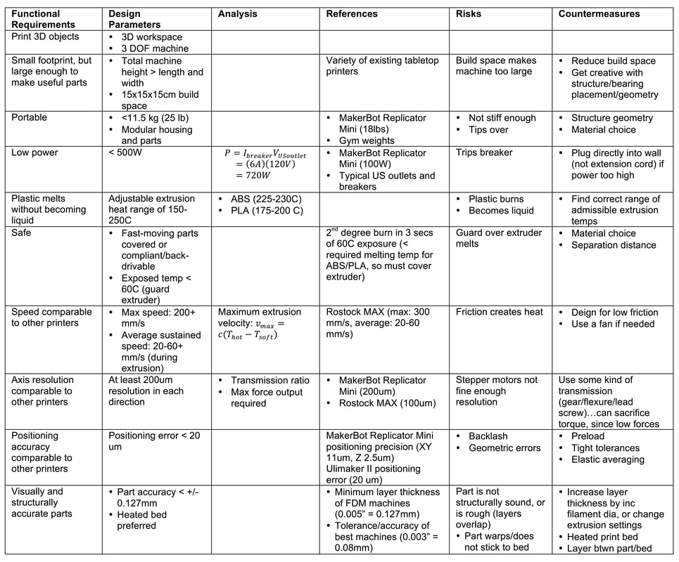
functional requirements and design parameters
The table below outlines the parameters, constraints, and considerations that I used to guide my design.
forward and inverse kinematics
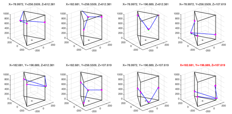
Because the "axes" are actually three parallel rails, a command to move the extruder to a particular cartesian coordinate must be transformed into carriage heights. Inverse kinematics (cartesian to carriage heights) are simple, because an input of desired [X, Y, Z] produces only one possible solution of carriage heights [Az, Bz, Cz]. Thus, the computation time is shorter. This is fortunate, because inverse kinematics is the direction that the printer needs to calculate in order to traverse a particular trajectory. It is still necessary to compute the forward kinematics for geometric error budgeting. Although the equations for forward kinematics are simple, they must be solved as a system in MATLAB. Solving for X, Y, and Z produces two results for each variable. We then have to run each XYZ permutation (there are eight permutations) into the inverse kinematics equations to figure out which one procures the original inputted carriage heights [Az, Bz, Cz].
Below is an example of the 8 permutations of possible extruder locations based on a forward input of [Az, Bz, Cz] = [200, 400, 600]. The correct result is shown in red on the bottom right, with coordinates [X, Y, Z] = [182.7, 196.7, 107.6].
Below is an example of the 8 permutations of possible extruder locations based on a forward input of [Az, Bz, Cz] = [200, 400, 600]. The correct result is shown in red on the bottom right, with coordinates [X, Y, Z] = [182.7, 196.7, 107.6].
The notebook excerpt below shows the calculations and reasoning I used to define and solve these kinematic equations. Using these equations, I was able to simulate any trajectory using MATLAB. A sample simulation is shown in the animation video at the top of this page.
|
Delta Linear Kinematics by Jess Ong on Scribd |
error budget
When designing a precision machine, it is important to use functional requirements to determine an overall maximum allowable error in the machine. An error budget can then be created to keep track the cumulative errors in all three dimensions based on factors such as thermal expansion, straightness tolerances, beam stiffness under load. Most of these errors can be modeled and predicted. Below is a notebook excerpt explaining the thought process behind settings up an error budget for the 3D printer.
|
Error Budget by Jess Ong on Scribd |